5. Scheme Management
After you have segmented the text, you will need to provide a scheme
(unless you specified an existing scheme when you loaded the
text/codings). Click on the Scheme button on the top toolbar to change to
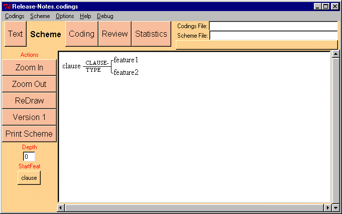
the Scheme Management interface. You will be presented with something like
the following.

Figure 3: The Scheme Interface with a new scheme
When importing the text file, the program asked you to specify a feature
to describe all units you are coding. In this case, I specified 'clause'.
You now have to enter a coding scheme, the heirarchical organisation of
the features you wish to use to code your text. The system starts with a
minimal 'dummy' scheme, which you have to modify and extend to make your
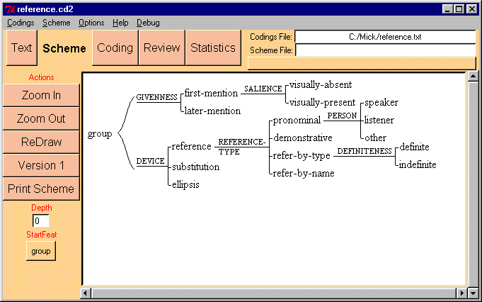
scheme. Figure 4 shows a more extended scheme.

Figure 4: A more complex scheme
5.1 System networks
The Coder uses the heirarchy representation from Systemic Functional
Linguistics. The heirarchy is called a system network. It
consists of a number of inter-dependent choice points called systems.
The dummy system shown in figure 3 is one such.
A system consists of three parts:
- system name: the name of the choice. Typical names in grammar
may be MOOD, POLARITY, FINITENESS, etc. The system name in figure 3 is "SYSTEM1".
System names should consist of a sequence of letters, and perhaps
numbers and hyphens, but no spaces within the symbol. The system name
needs to be unique - the Coder will not allow you to provide the same
name for two systems. The program will automatically display systems in
upper case.
- features: the alternatives in the choice. In the above
example, feature1 and feature2 are the features of the system. These are
displayed in lower case, regardless of how you type them in. A feature
can only occur in one system.
- entry-condition: each system has an entry condition, the
feature (or complex of features) which forms the context in which the
choice becomes relevant. In the above case, the entry-condition for the
system is clause, which happens to be the root-feature of the
system network.
Several systems can have the same entry-condition, in which case, the
systems are called simultaneous systems. They form a cross
classification of the entry-condition. For instance, we might introduce
another system with clause as entry-condition, which might have
features finite and nonfinite.
The set of systems that you define form a system network, with
the features of one system forming the entry conditions for more specific
systems. How you can create these networks is described blow.
5.2 Creating & Modifying Systems
If you click on one of the feature (lower case) or the system (upper
case) of the network, you will be presented with a popup menu of actions.
These allow you to extend or modify the network.
5.2.1 Actions on Systems
- Add Feature: adds a new feature to the system.
- Rename System: allows you to change the name of the system.
- Delete System: deletes the system from the network. Note: the
features which belong to the system, and any systems which depend upon
them will also be deleted. And there is no undo at present. If
any codings have been assigned these features, the features will be
deleted from the codings.
- Change Entry Condition: change the entry condition of the
system from one feature to another.
- Move Up: moves the system higher up in the graph, to
reorganise the layout.
- Move Down: moves the system lower up in the graph, to
reorganise the layout.
- Ignore/Unignore Subnet: [New] Disables
the system and those which depend on it. The disabled systems will be
shown in gray. They will be ignored in coding and statistical analysis.
Ignored systems can be unignored by selecting the ignored system and
choosing "Unignore subnet".
5.2.2 Actions on Features
- Add System: creates a dummy system under the feature.
- Rename Feature: changes the name of the feature.
- Delete Feature: deletes the feature from the system. Note:
the any systems which depend upon this feature will also be deleted. And
there is no undo at present. If any codings have been assigned
to the deleted features, the features will be deleted from the codings.
- Move Up: moves the feature higher up in the system. Note that
the first feature in the system is the default in coding.
- Move Down: moves the feature higher up in the system.
- Edit Realisations: [New] You can add realisations
attached under features. The program doesn't do anything with them, but you can use this feature to annotate features, e.g., with a gloss of the choice.
- Show Examples: [New] Selecting this option will move you
to the Review interface, with the filter set to the feature. Only those codings which have the feature are thus shown.
5.2.3 Changing Entry Conditions [New]
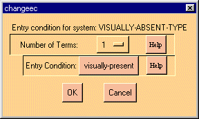
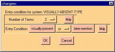
To change the entry condition of a system, click on the system, and select "Change Entry Condition". You will be presented with a
dialog box as in figure 5.


Figure 5: The Change Entry Condition Dialog: simple and complex
Simple Entry Condtion: If you want a simple entry condition (the system extends from a single feature),
then set "Number of terms" to 1, then choose the feature you want as the entry
condition. Press "OK" and the graph will be redrawn as specified. The Coder
will automatically update the codings which are affected by the change.
Complex Entry CondtionYou can also introduce complex entry
conditions into your network. A complex entry condition involves a
conjunction ('and') or disjunction ('or') of features. Set the number
of terms to 2 or higher. Then select the features you wish s the
input. Note that at present, you cannot mix AND and OR in the same
entry condition. You can simulate such by first making a 'gate' (a
system with only one feature). For instance, to construct the entry
condition 'A and (B or C)', first make a system with one feature (call
the feature b-or-c). Then use this feature and the A feature in an AND
entry condition for your original system. The entry condition for this
system will now be 'A and (B or C)'.
5.2.4 To Move a feature to another system
If you want to move a feature from one system to
another, click on the system you wish to add the feature to, and select "Add
Feature". Then type in the name of the feature you wish to move. The
feature will be moved to this system. All codings will be adjusted for the
change.
5.3 Printing Schemes and Exporting for Inclusion
in Documents [New]
To send your network to the printer, click on the
"Print Scheme" button. Note that the printing is unreliable at
present, and may truncate larger networks.
To save a postscript version of the network,
which can be included in Latex documents (but maybe not in MS Word at
present), click the "Save PS" button.
To save a version of the network in pdx format,
click the "Save PDX" button (Scheme interface). This format is
useable for PC users, and in conjunction with the MDraw program, allows
inclusion of scheme diagrams in MS Word or other word processor documents.
See the instructions for use in section 2.4.
NOTE: I haven't yet perfected the export of curly
brackets to pdx. You may have to draw these yourself within MDraw.
For more details on printing and exporting your networks, see here


